
ArcSys Style ARCSYS STYLE
Here I will go in-depth on how to add a custom shading model into Unreal Engine 5.2, and modify it to behave similarly to Arc System Works' shader for their recent games. But first a showcase!
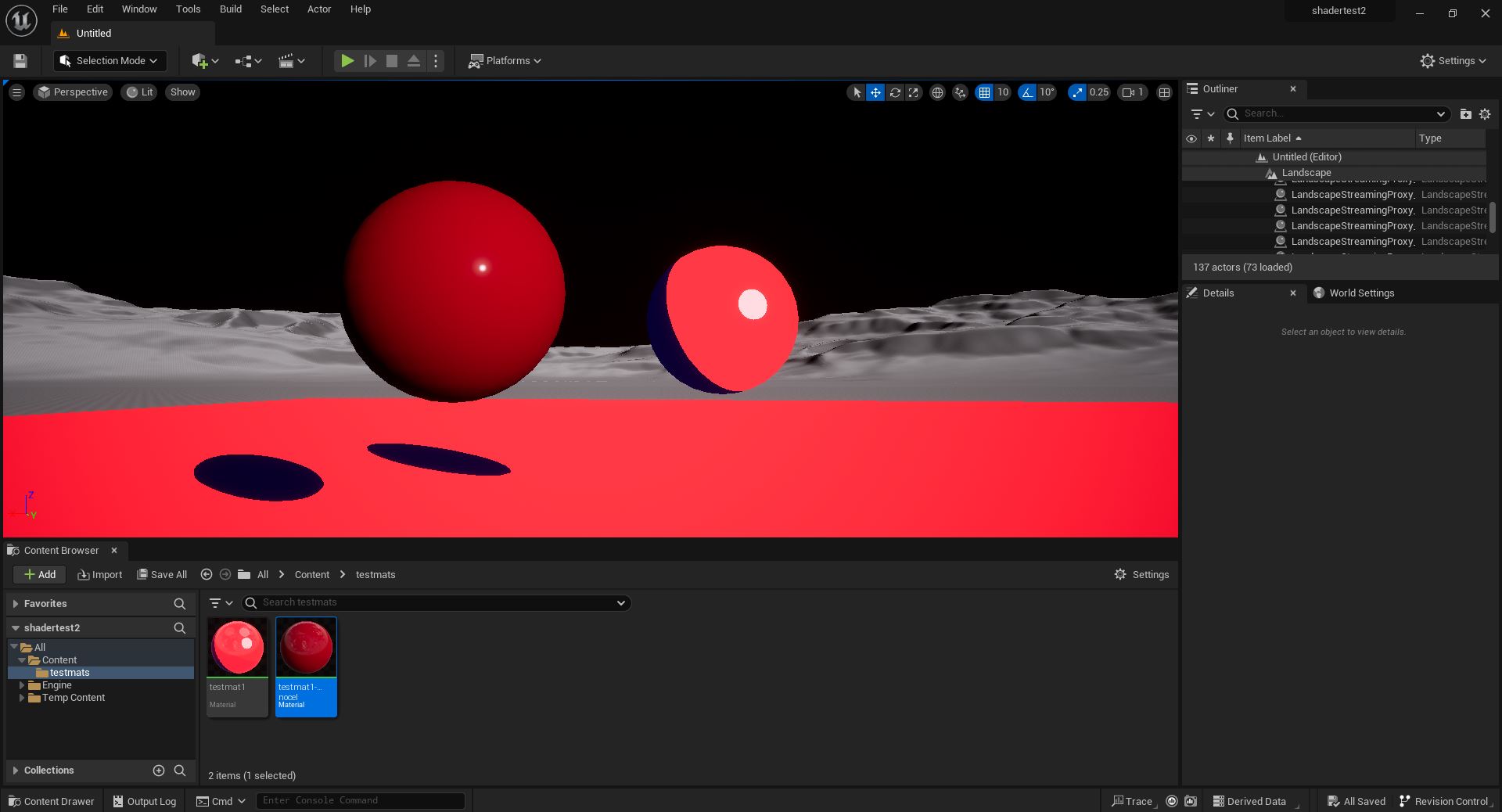 ^ Showing my toon shading next to a regularly "Lit" shaded ball. Notice how the shadow on the ball (and the cast shadow on the ground!) is slightly tinted blue - I added a custom "shadow color" control that allows you to multiply a different color over just the shaded areas to give more visual interest and vibrance.
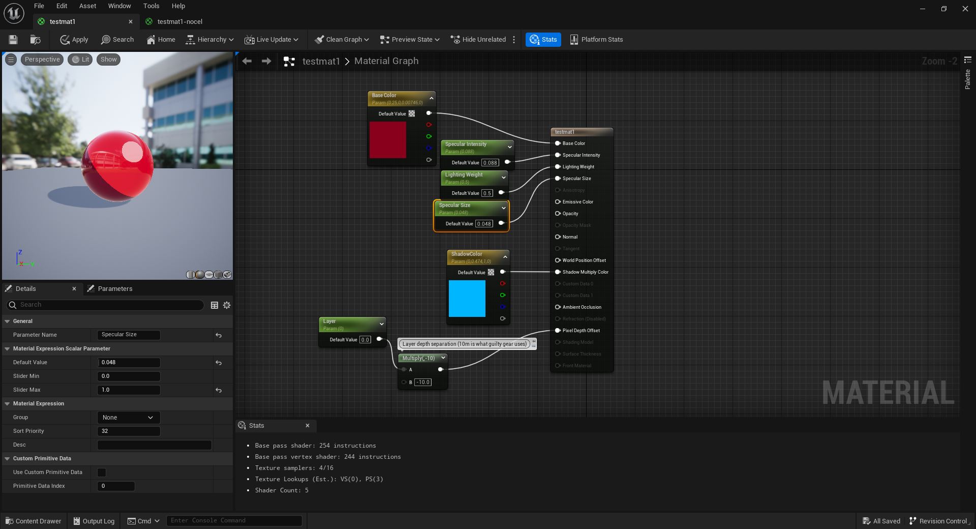 ^ What the material editor looks like for that material. Notice - no tricks! Just color, shadow colors, and some lighting controls. (and a z-buffer offset but that's irrelevant here). It looks different in the preview editor because reflections are forced on.
 ^ It scales with light intensity and radius...
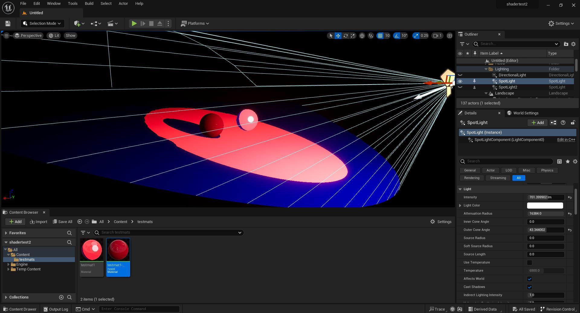
 ^ Works with multiple lights...
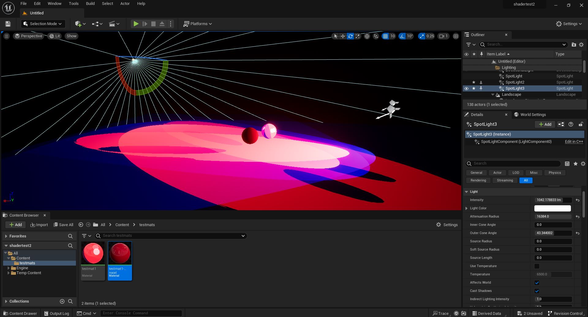
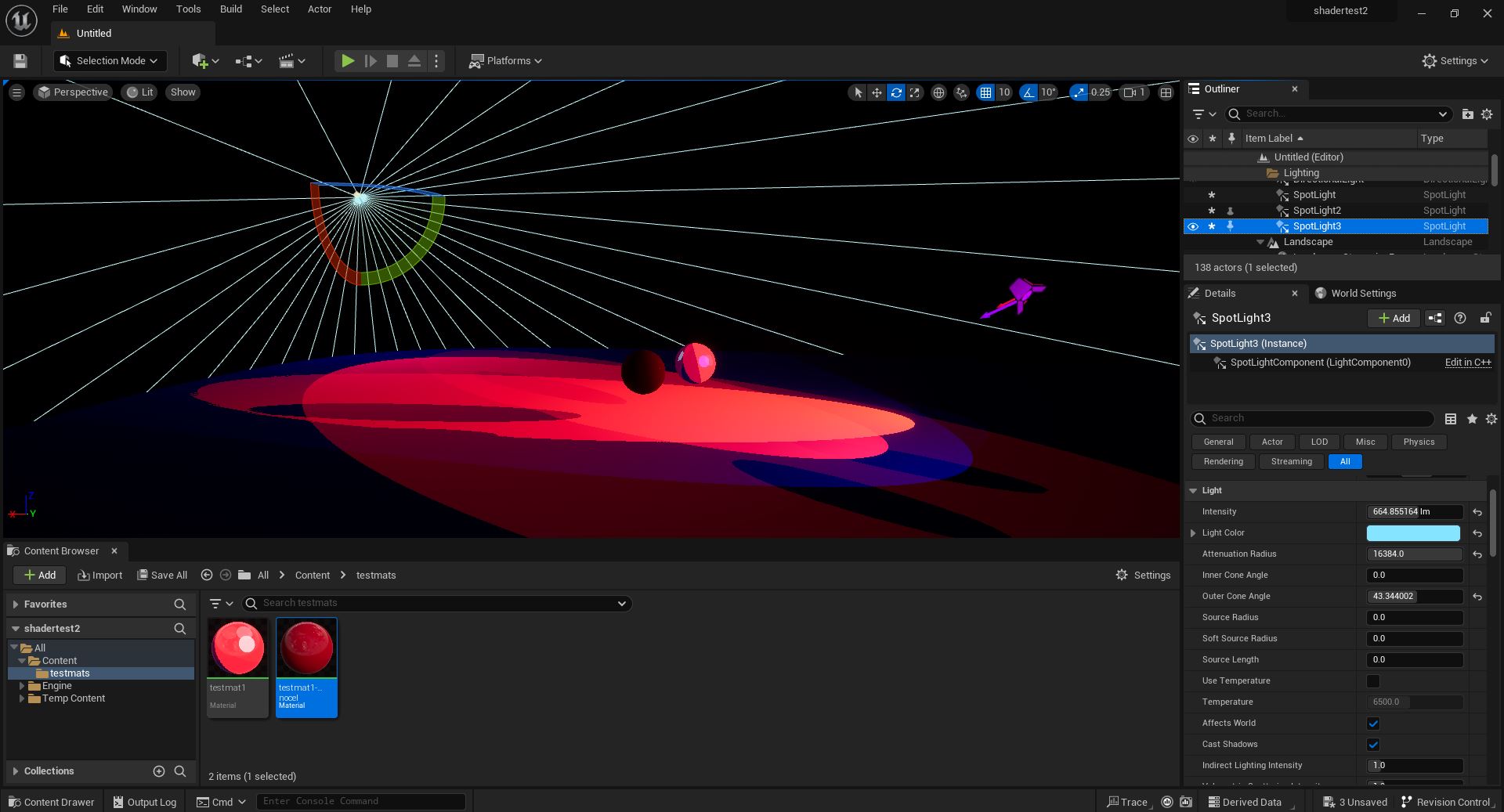 ^ And even different colors of light! (though it's harder to tell because the object colors are almost pure red and pure blue, meaning the greens get almost entirely multiplied out. I promise one of those is a green light! This may seem odd, but remember - if you have a monocolor light source in real life, this same phenomenon will happen! This is just moving that phenomenon to the object color instead of the light color.)
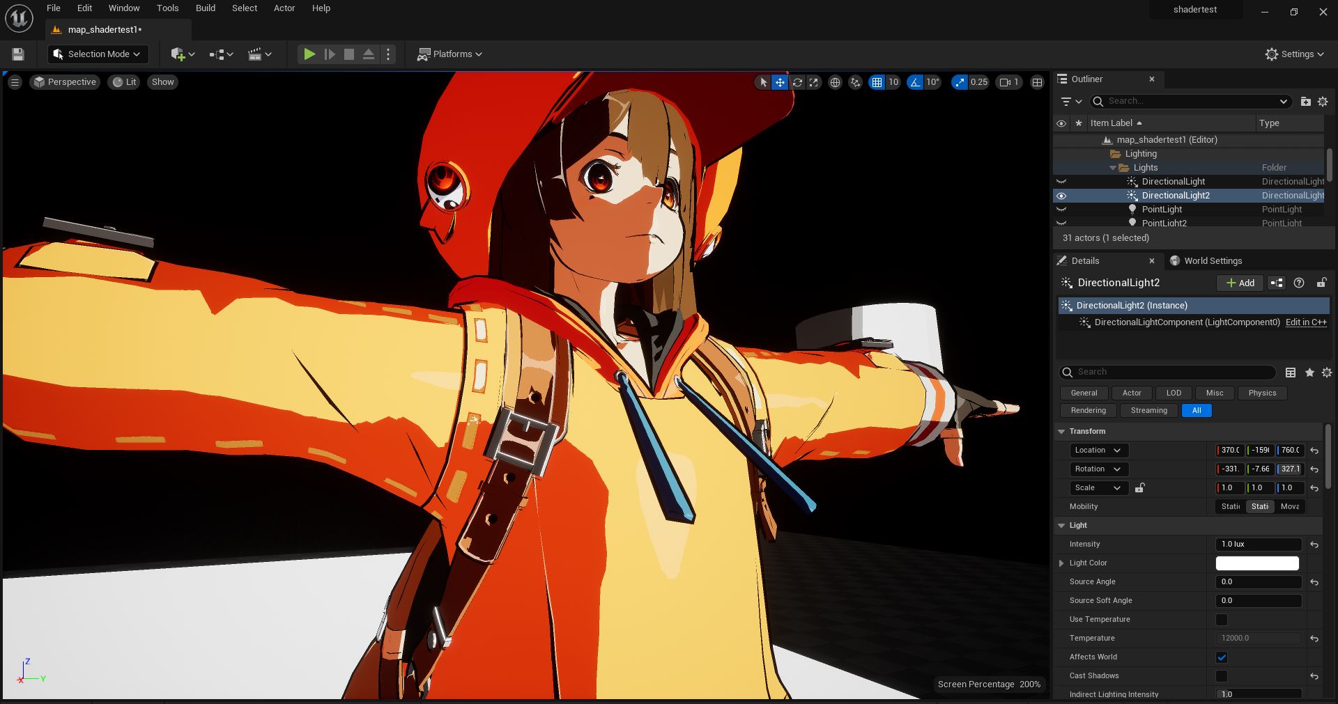
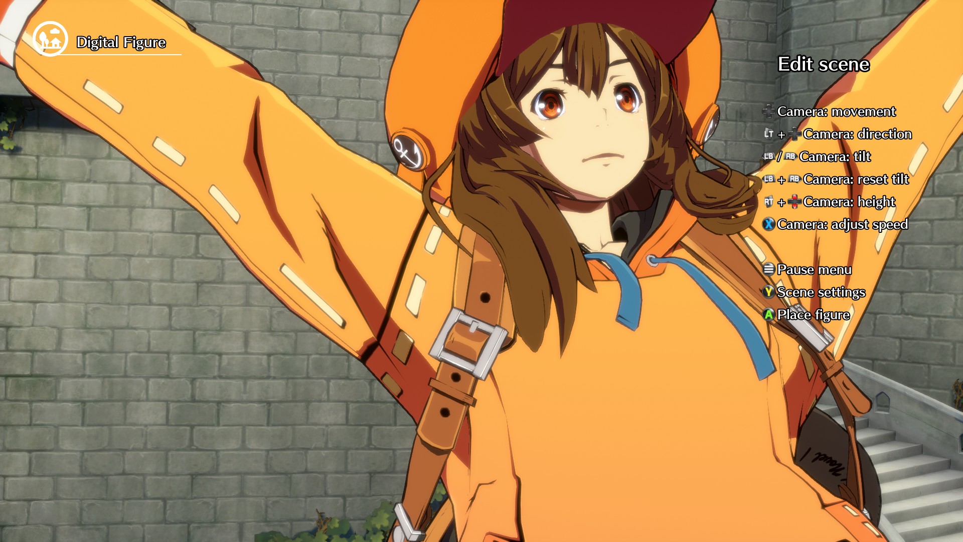 ^ A comparison between my model and the GUILTY GEAR -STRIVE- model viewer. Of course, the pose and lighting are different, but take special note of the shaped specular on the backpack strap! How the highlight bows outwards on the buckle - I'd say I've just about nailed it! And yes, my highlights are brighter - particularly in shadow - but that's intentional by me. I like specular to pop! But I've added multiple ways to adjust it to the taste of whoever uses this.
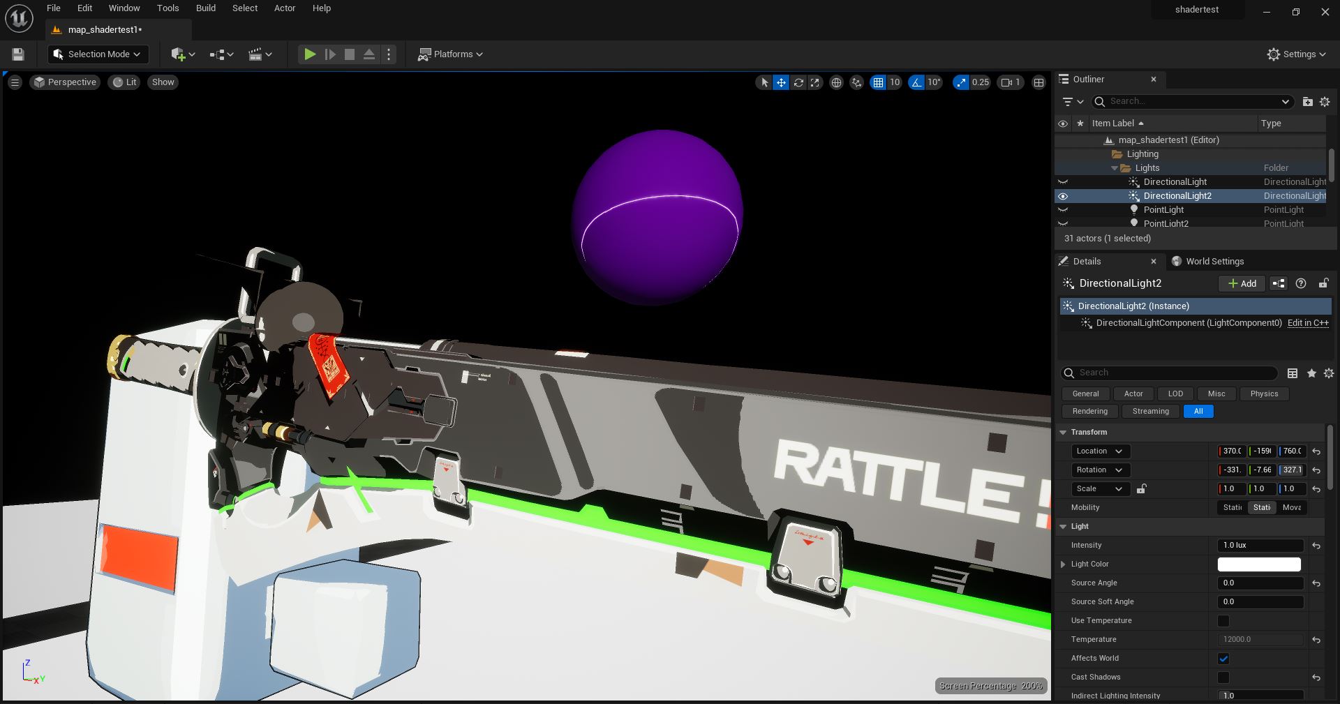
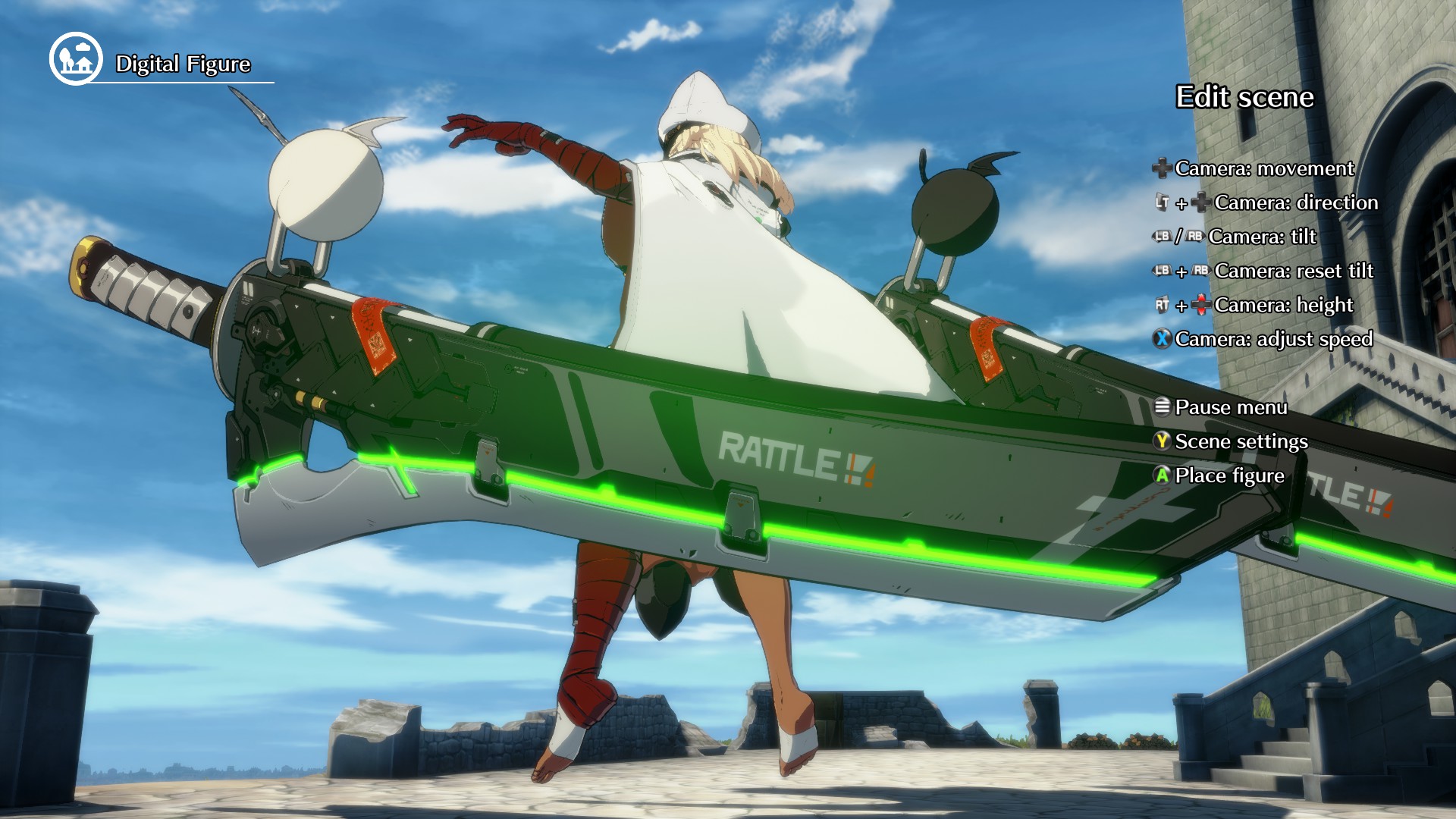 ^ Another comparison to show that I've got the specular calculation pretty bang-on. The highlights on the handle don't match, but that's actually because the sword in GGST is curved! They will often distort things to make things work from a certain perspective. I had access to the GGST models & textures but not the rigs, so I couldn't replicate this curving - but the specular on the blade looks very similar!
 ^ This is a simple model I made following the Guilty Gear process as closely as I can, documenting it as I go along. My documentation will be at the end of this page! You can see the shaped specular working here too!
 ^ Here you can see the shaped specular interacting with the "regular" specular, as well as my custom normals. His front is entirely flat, but he's shaded as if he's got a little curve to him - This is all done by editing the normals to average out between corners of the model. This gives a REALLY pleasing transition on flat surfaces that I absolutely love.
 ^ I even managed to replicate the "infinite resolution line" trick that Arc System Works pioneered in Guilty Gear Xrd -Sign-! This is the trick that really sent me on my whole gamedev journey. That line really is "infinite" in resolution - it's axis aligned in UV space, so that no matter how far you zoom in, a texture sample will always interpret a clear edge to that line!
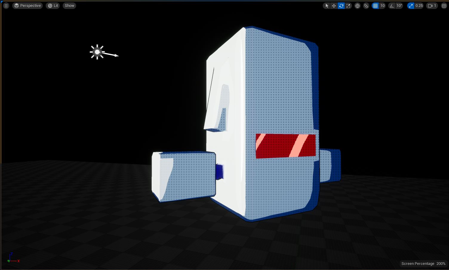 ^ This is just having fun at this point, but here I can show that you can really do anything you want with lit and shaded areas. The dots are screen-space, and are applied only in shadow - something Persona 5 does in some of it's graphics - and the blue tint on the edges is a Fresnel effect, but also applied only to the shaded regions. The light is coming almost perpendicularly from the left.
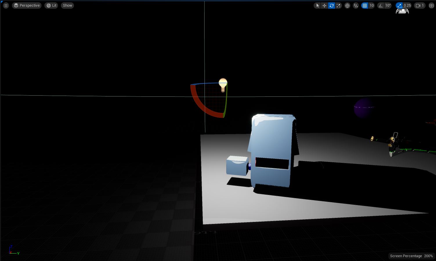 ^ I'm really happy with the cast shadows. Also in this picture is a slight gradient to the object - that's not coming from the light, though it WILL react to the light's color. Same trick as the above image, just applying it to the lit regions instead of the shaded regions. Having all this stuff on a per-object basis and controlled by some easily-paintable textures makes it really quick and easy to get very detailed lighting on any object!
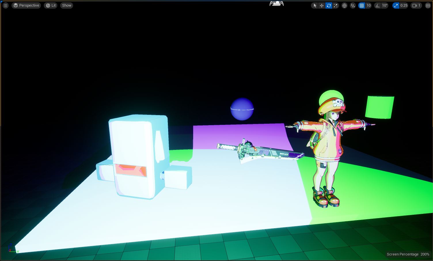 ^ And finally, a better showcase of colored lights featuring my whole cast of test subjects! Notice how the purple and green lights interact on May's coat - the way they blend is just SO good! You can do "traditional" multi-colored stage lighting setups (like what you might find in a theater) and they will work, but also pop WAY more than they would in reality, while not creating any ugly color blending areas or muddiness to the color!
//
All in all, I’m really proud of this. I’ve reverse engineered both Unreal Engine and Guilty Gear to get a very close approximation of not only their technology, but also their workflow - and if you want to find out about how I did it, read on!
//
- PART ONE: HIJACKING UNREAL ENGINE’S DEFERRED RENDERER FOR FUN AND PROFIT
You can set custom pin names in “GetAttributeOverrideForMaterial” in “MaterialAttributeDefinitionMap.cpp”. Each pin is given a Case in a Switch statement, and you can simply copy the format of those cases having “CustomPinNames.Add()” in them, being sure to reference your shading model and preferred name for the node.
- PART TWO: CREATING ASSETS TO TAKE ADVANTAGE OF YOUR BRAND NEW SHADING MODEL
First, this must start with a disclaimer: ALMOST ALL OF MY 3DCG EXPERIENCE IS IN AUTODESK MAYA. This is all done in Blender because a few years ago I finally ran out of student emails to get free copies of Maya with. My expertise in Maya is all in rigging & shading, and although I do know how to use the modeling tools, I am certainly not a good artist with them. This does use a few nifty Blender plugins, but for the most part the procedure is almost the same in Maya. I just can’t show it because my license ran out. Anyways, on with the show!
/ BELOW IS A DIRECT, UNEDITED SAMPLE OF MY OWN PERSONAL DOCUMENTATION I WROTE FOR MYSELF WHILE GETTING THE WORKFLOW DOWN /
CHAPTER 1: POST MODEL CREATION to FINISHED UV & TEXTURE MAPS I just finished my model, now what?
Assuming your model is final, and I really mean FINAL, because this technique is a pain in the butt, the first thing you want to do is UV Unwrap your model. Head to the UV editing tab and begin marking seams on your model.
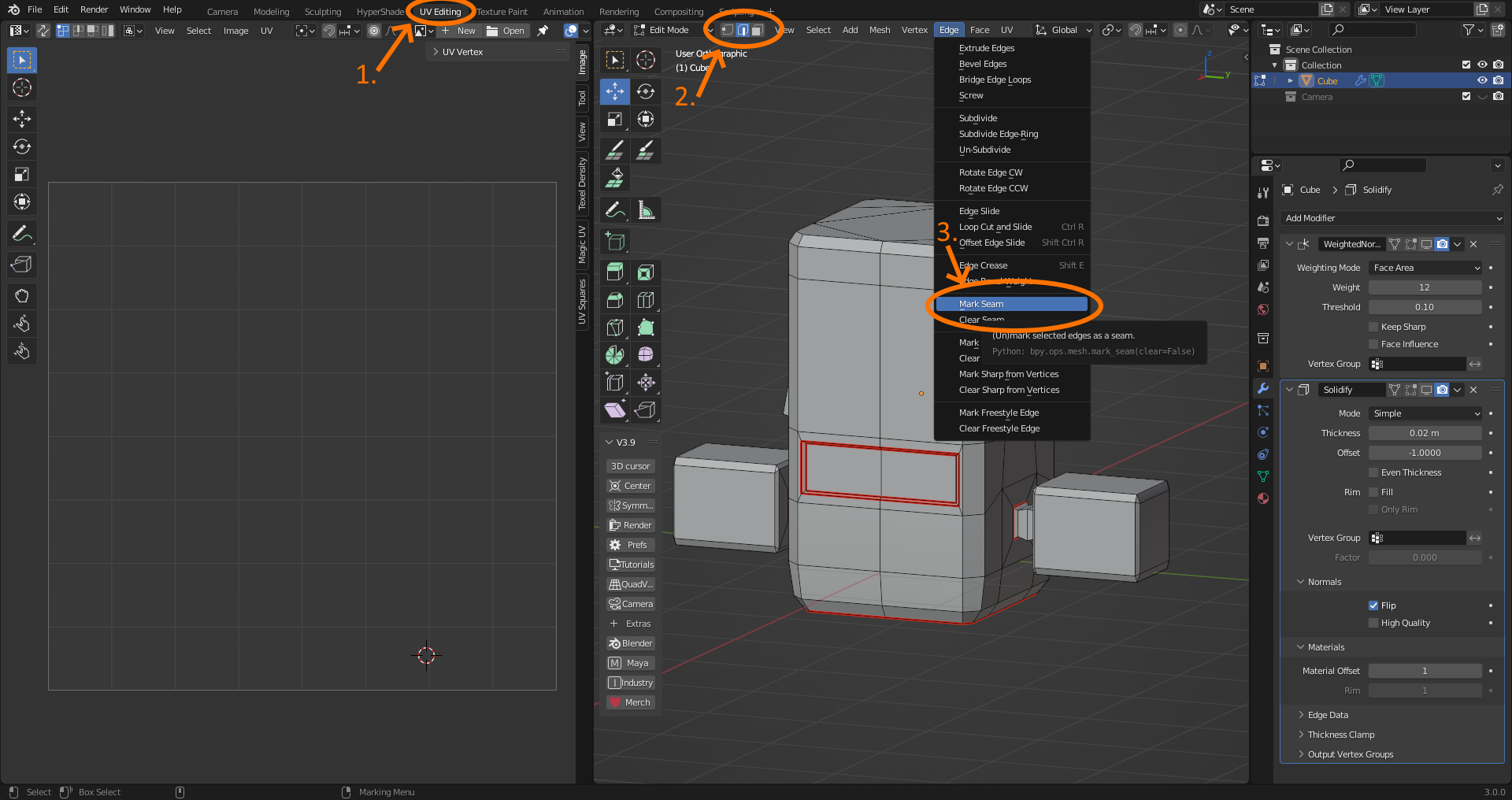
You MUST mark a seam wherever you want there to be an anime-style hand drawn line, and ideally you should just mark off the different sections of your model, but we will be using an automated UV unwrap which should handle a good portion of it. Once you have you’ve marked your seams where you…
- Want hand-drawn style lines
- Want to separate color portions of the model
- Want to practice good UV habits (not required)
Go to face mode, hit A to select all, go to UV, and hit either “Smart UV Project” or “Cube Projection”. I like to use “Smart UV Project” with a threshold of 89 degrees, but either method should work.
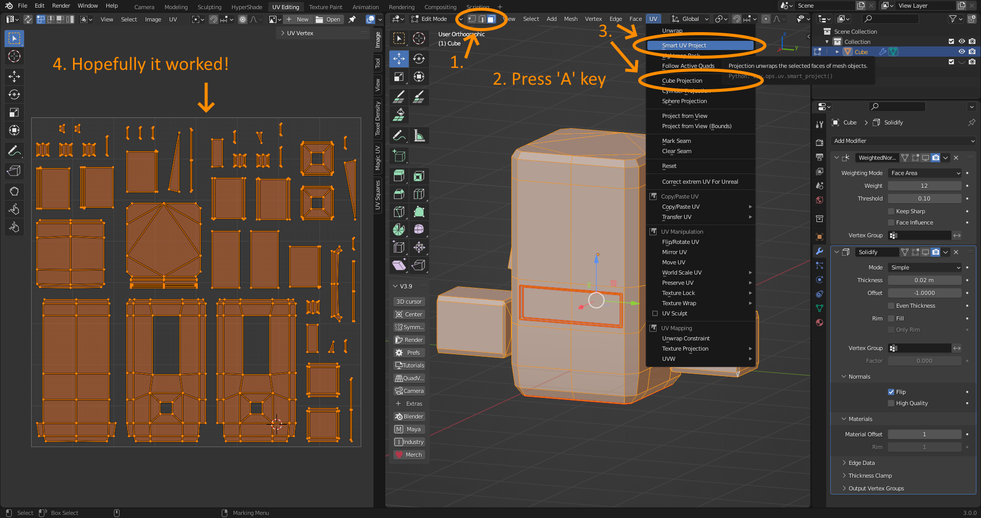
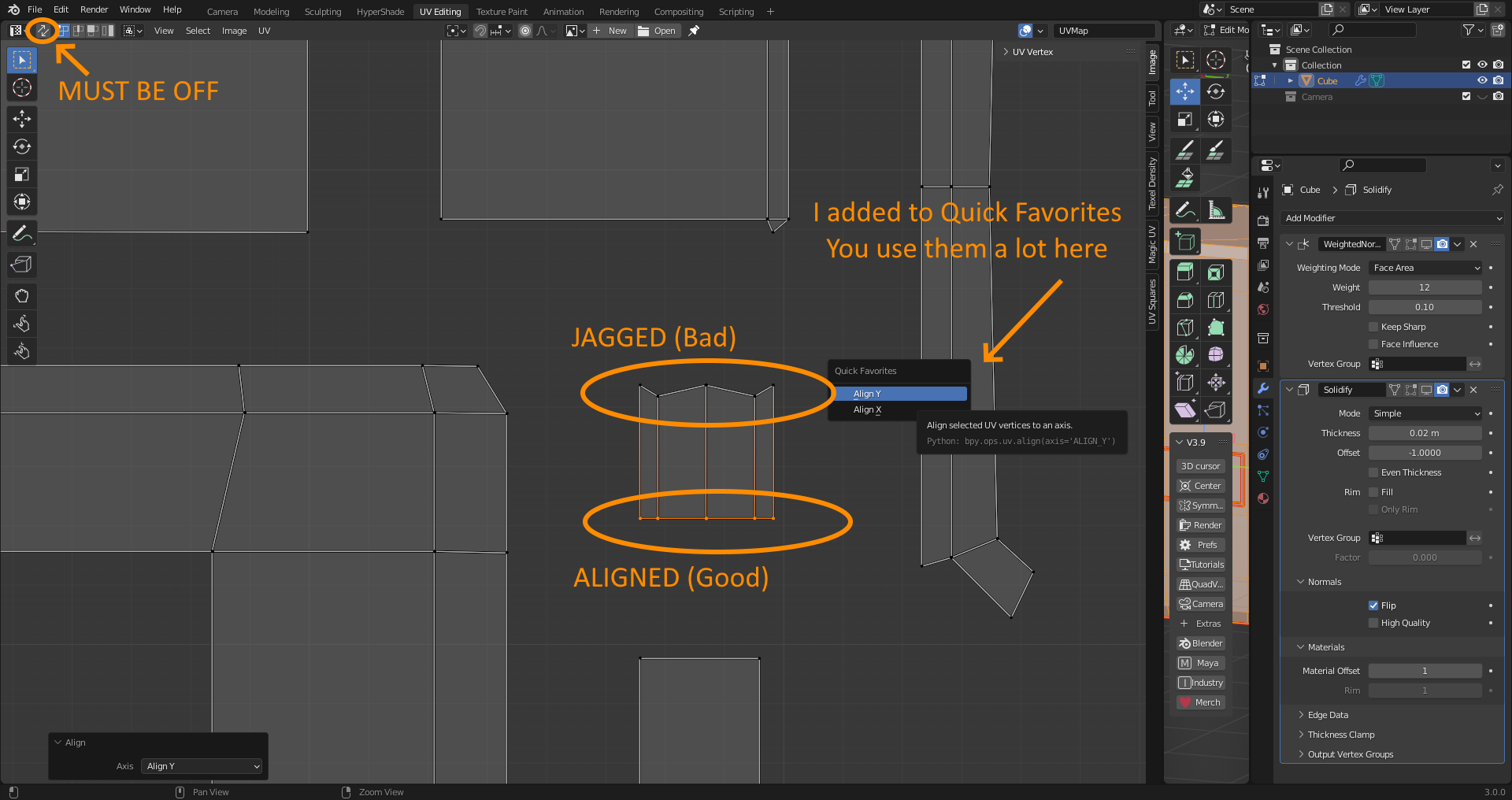
To know if it worked, everything should be unwrapped into pretty sane pieces - no crazy stretching or overlapping going on. It doesn’t technically matter, but it’ll save you a lot of pain. To view stretch, you can go up to the two circles in the UV panel, and hit “Display Stretch”. Now, the most time-consuming part: you must eliminate everything that isn’t aligned to an axis-perfect 90 degree angle. It’s important to not that you MUST be in Vertex mode in the UV editor to do this - and you MUST have “UV Sync Selection” (the 2 arrow icon in the top left) turned off.
What you now must do is find any vertices that aren’t aligned to a perfect vertical or horizontal line, select them all, go to UV, Align, and then either Align X or Align Y depending.
Now, do this across every…
- Outer line of a UV Island (the inside of a UV island can be as distorted as you want)
- Seam you want to have a line on
Okay, yeah, you don’t need to do this to every line, but you should do all the ones that you deem important. It’s a lot easier to do more than you think you have to now, than go back and edit this later. (The UV map is awful to edit later so it’s worth spending time on).
Now is also a good time to organize your UV layout - find out what islands belong to the same pieces of an object, and group them together in ways that please you. Again, this isn’t necessary, but it’ll save you a lot of headache. “Smart UV Project” works pretty well, but it’s not very good at keeping similar parts of the model together.
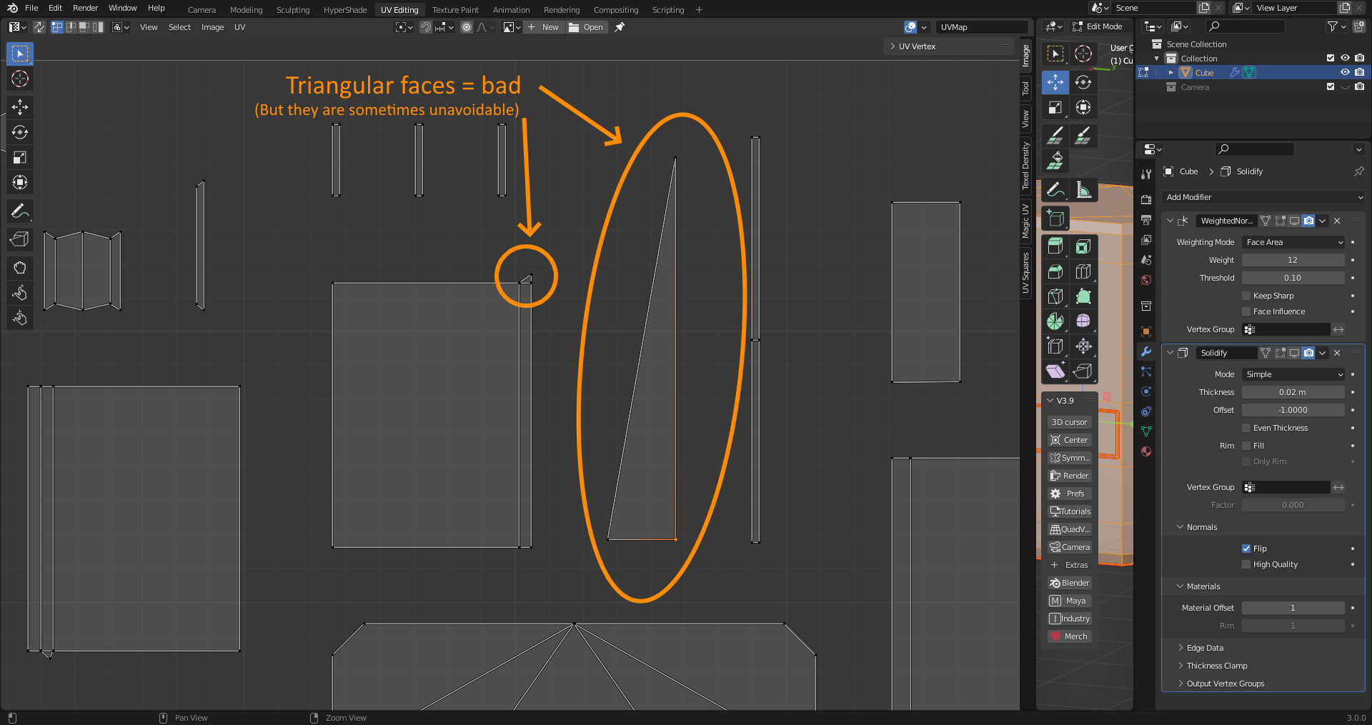
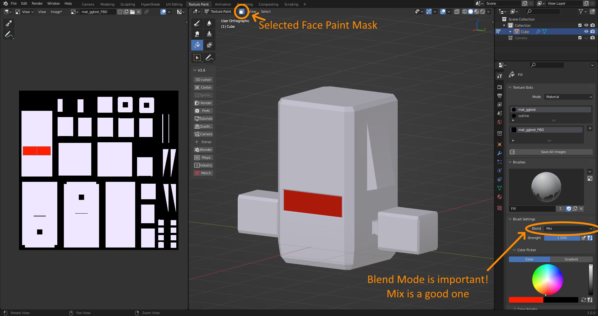
Triangular faces are unavoidable, and when this happens you will just have to pick 2 edges to axis align, and accept you will NEVER be able to have a clean edge on the non-aligned one. If you have an edge you really want to outline, make sure it’s on a quad face, or simply make sure you don’t want to outline 2 opposing faces of a triangle. You should try to make the model with all this in mind, however - but making quads isn’t too hard in most cases, so you should be okay. Once you’ve done all that, the hard part is over - the rest is pretty fun. Namely, the next part - going ham with the fill tool in texture paint mode. Open Texture Paint mode, open a new image, color pure black, no Alpha, and generated type Blank. It can be any resolution, but I recommend a higher resolution for more flexibility. Also, I’d suffix the file name with _FBD - standing for FullBright Diffuse - because it’s what I’m gonna be using, and it’s descriptive.
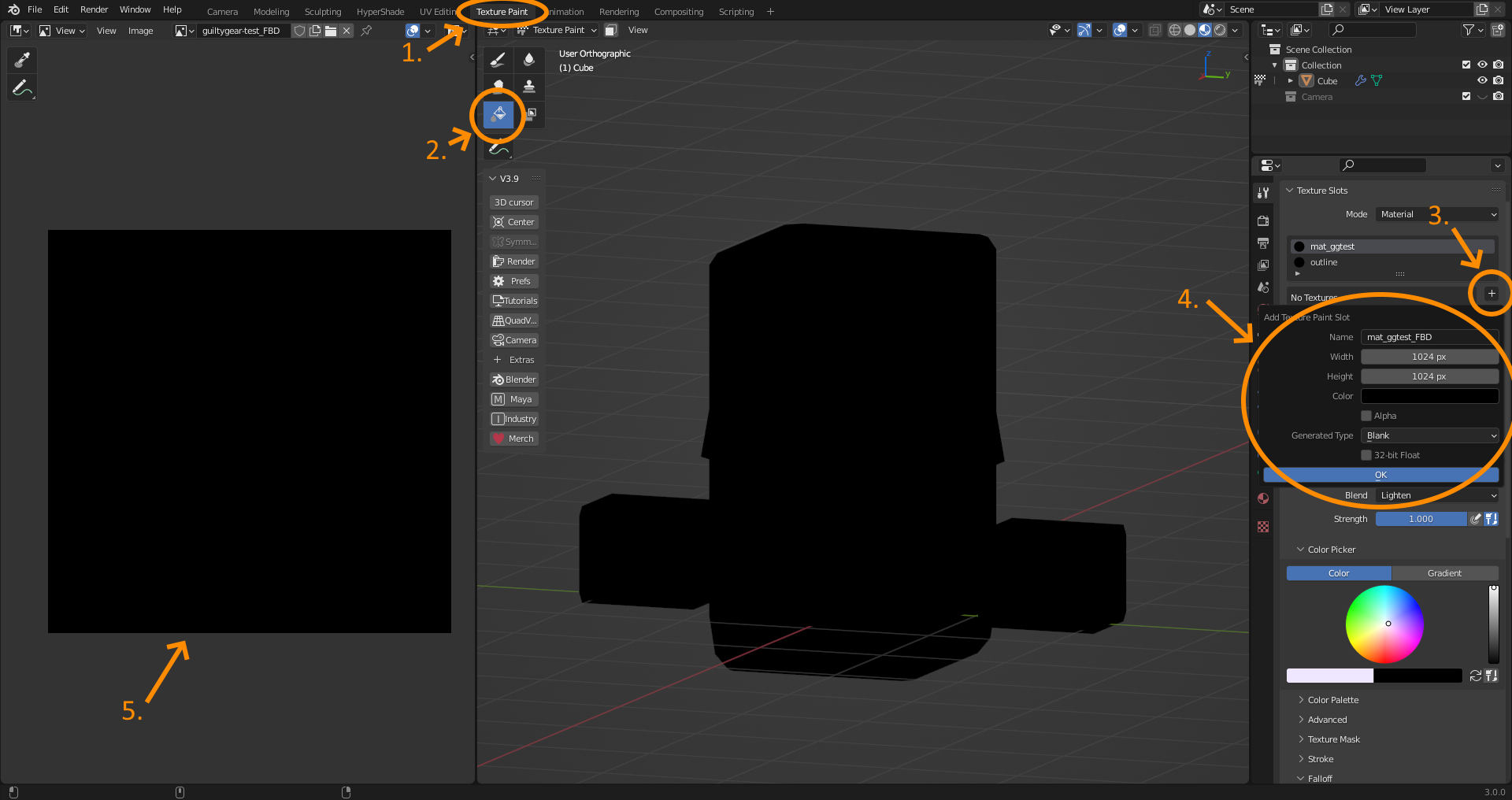
If you’ve ended up with your model completely black, that’s a good sign. Now it’s time to go ham with the fill tool! You can use an external image editor for this, but I will use Blender’s own texture painting tools.
First, select the fill tool, set Blend to Mix, scroll down to options, and make sure Bleed is set to 1px. After this, begin to paint your model with the fill tool.
You can also swap back to edit mode, select faces, and then use the selected faces as a mask in Paint mode.
Now would be a good time to apply a “WeightedNormal” modifier, usually set to a low number (I like 8-20 usually), just to see how it’ll look with a bit more “stylized” normals. After that, do exactly the same, but this time painting the shadow color on a separate texture (Called the SSS map, for SubSurface Shadow)
After that, we paint what’s called the “ILM” map - in Guilty Gear, I think this is Vertex Color, but we can pack it into a texture here because their actual ILM was black and white and I don’t want to deal with Vertex Color - Ahem, I mean - I’m “leaving vertex color channels open for other uses.”
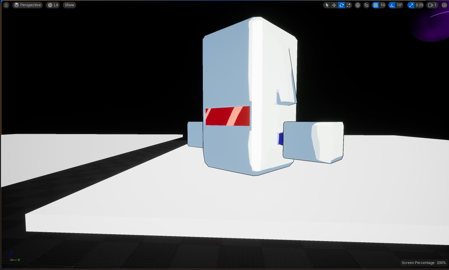
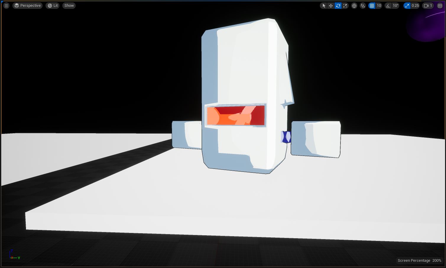
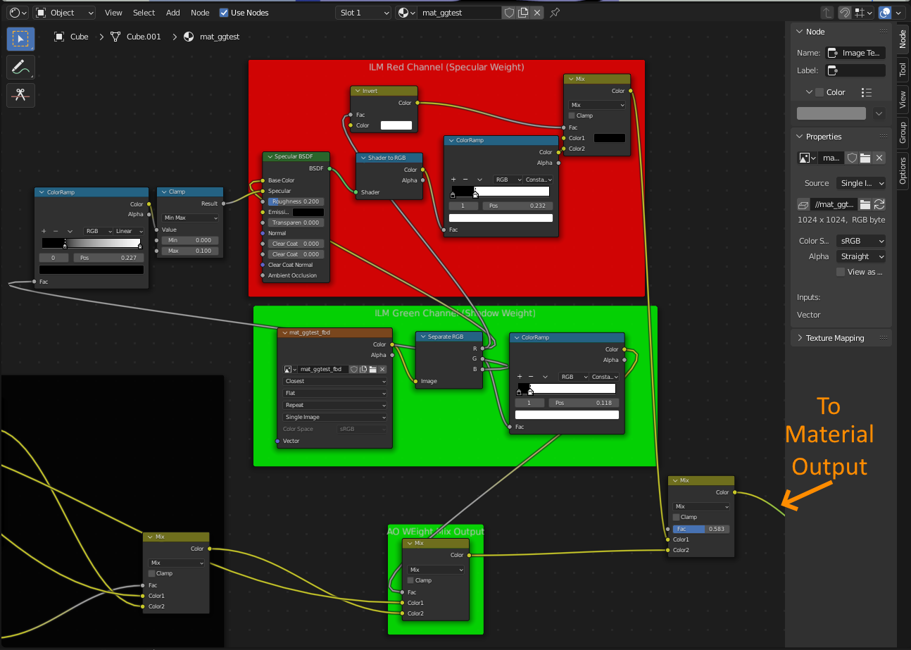
Anyways the ILM map is a bit more complicated - though actually a bit simpler - but it’s colors aren’t “real” colors. Instead it’s colors are used to drive different lighting values (namely how much something should be highlighted or shadowed). Here is an example of an ILM:
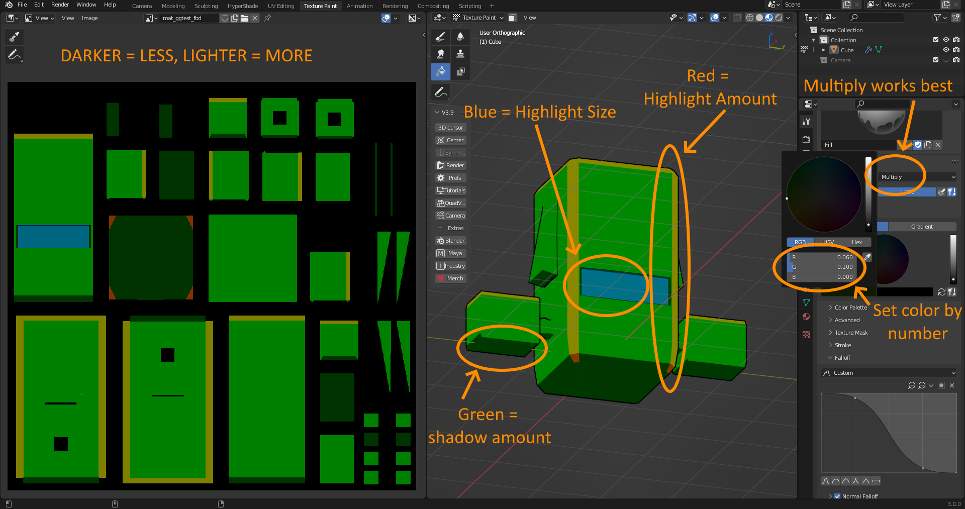
GREEN = How likely an area is to get shaded.
- Darker = more shadow / Lighter = more light
RED = How bright a highlight is
- Darker = less highlight / Lighter = more highlight
BLUE = How big a highlight on an area is
- Darker = smaller highlight / Lighter = larger highlight
In the above example, I set up darker green patches on all the bottom-facing areas, so the bottom of the model remained in shadow more consistently.
I set green + red strips on the corners, because I still want those areas to be shaded normally, but I wanted there to be more of a highlight on the edges because I think it looks cool.
And I set a slightly darker green + blue patch on the visor, because I want it to get shaded a little less than the rest of the front (because it’s inset), but I also want the highlight on it to be nice and fat to really sell the “visor” part of it.
If you were doing this in something like Photoshop, you could edit each color channel individually and merge it together later, which would make this a lot easier, but it’s not too difficult in Blender so I’m doing it in there for now.
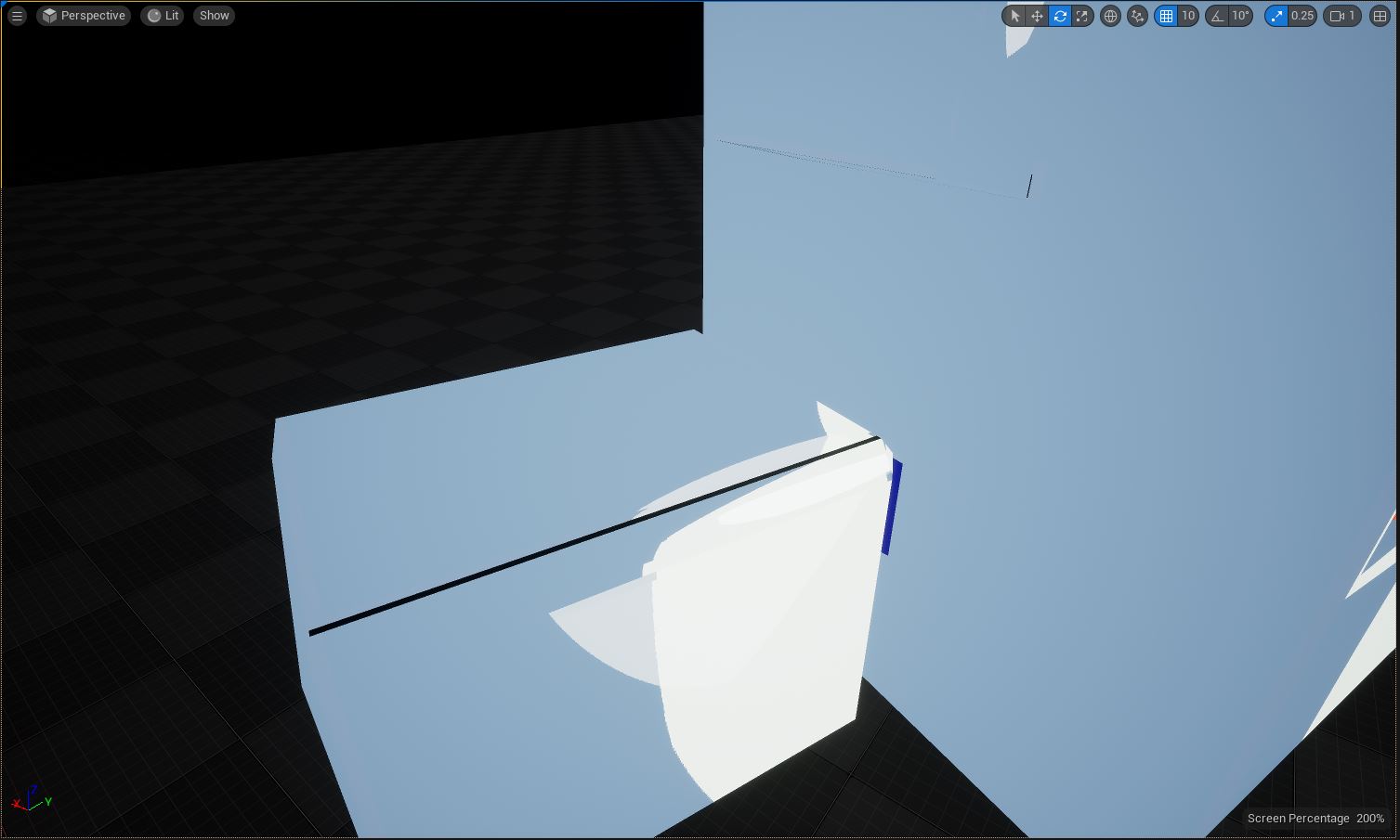
Anyways, the ILM actually contains a fourth channel - the Alpha channel - the reason it is called the Inner Line Map - the fact that it can create “infinite” resolution lines on a model.
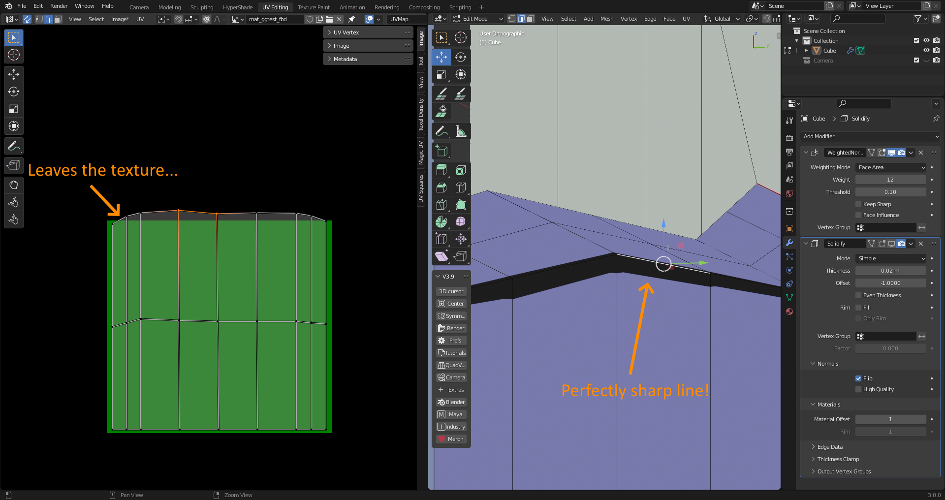
By “nudging” the UV map off the texture, as long as your texture is composed of perfect rectangles, it will create a perfect, “infinite” resolution line on your model. This can be controlled for a great, hand-drawn “inner line” look that Guilty Gear has made famous. If your lines aren’t as crisp as you’d like, you may need to subdivide that area of the model - at this point, the resolution of the line is dependent on vertices, and not pixels.
This doesn’t mean your model needs to be super detailed - you can start with a flat face, subdivide it a ton, and only use those extra vertices in the UV editor to drive lines.
Anyways, have fun, cause this part is really special. Imagine how you’d draw it with a pen, and then try to go for that - or even go for something completely different. It can even be a color other than black - but I don’t know how good that would look. (I’m gonna try it later though).
At this point, you’re technically done, but here’s the material setup in Blender if you want to preview it before Unreal:
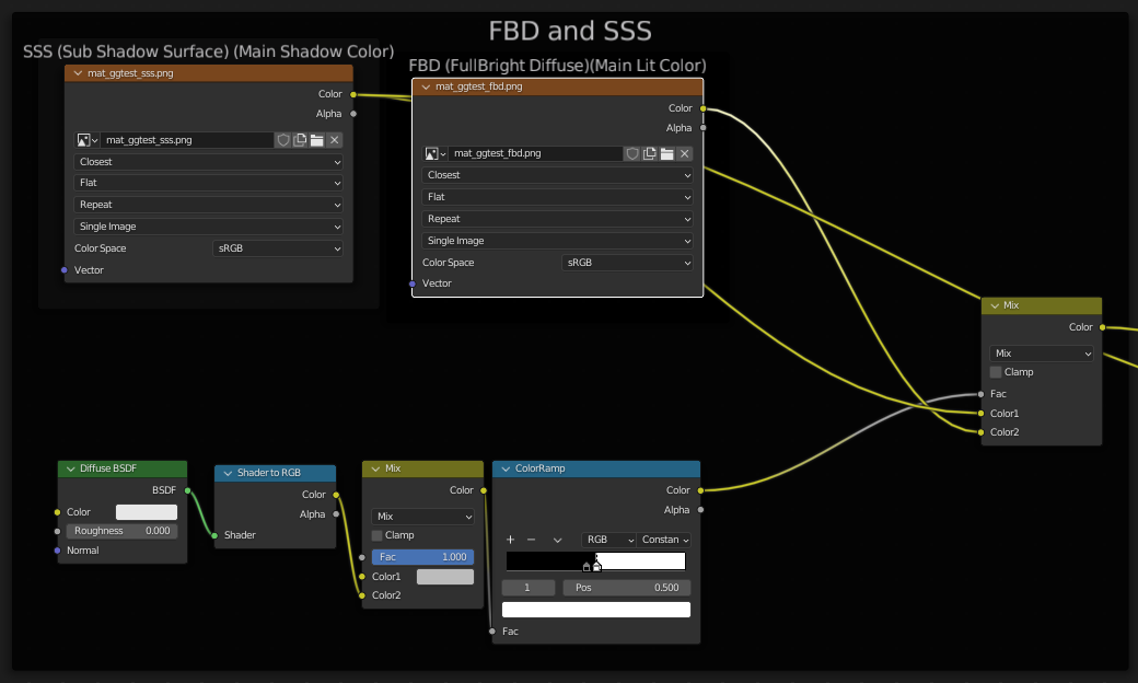
/ END OF DOCUMENTATION /
Of course in a professional environment there would be a lot less slang and anecdotes, but honestly I do love writing documentation for stuff. Figuring out how it all works and explaining it concisely is almost as fun to me as actually writing the code, so I don’t mind it at all.